
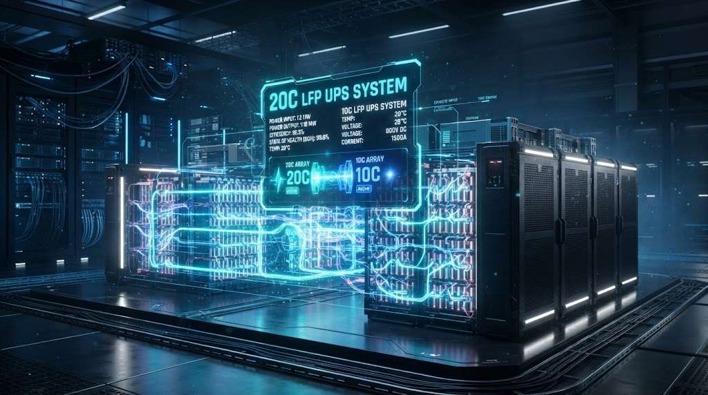
The AI Power Crisis No One Is Talking About
Your GPU cluster just lost utility power. In the 200 milliseconds before the UPS responds, your model training crashes. $500,000 in compute time evaporates. The generators start, but they need 10 seconds to stabilize. Your legacy lead-acid batteries—rated at 2C—cannot deliver the instantaneous current your AI infrastructure demands. The result? A cascade of failed nodes, corrupted checkpoints, and an angry call from the CTO.
This scenario is playing out across the industry. AI workloads have fundamentally rewritten the rules of data center power architecture. Traditional UPS batteries are failing under the relentless, spiky power demands of GPU clusters. The solution is clear and increasingly urgent: the high C-rate LFP UPS system—specifically 10C and 20C lithium iron phosphate configurations—delivers the extreme power density, millisecond response, and long-term reliability that modern AI facilities require.
This guide explains what 10C and 20C ratings actually mean, why older technologies cannot keep pace, and how to size, deploy, and operate these systems safely in 1–50 MW power rooms.
Understanding C-Rate: The Metric That Matters for AI Workloads
C-rate is the measure of how quickly a battery discharges relative to its rated capacity. It is the single most important specification for UPS applications supporting AI infrastructure.
| C-Rate | Discharge Time | Peak Power (100 kWh System) | Best Use Case |
|---|---|---|---|
| 1C | 60 minutes | 100 kW | Basic backup, low-density IT |
| 3C | 20 minutes | 300 kW | Traditional enterprise data centers |
| 10C | 6 minutes | 1 MW | AI training clusters, GPU racks |
| 20C | 3 minutes | 2 MW | Hyperscale AI, HPC environments |
For UPS duty, this translates into massive instantaneous power delivery. A 100 kWh 20C LFP cabinet can supply approximately 2 MW for several minutes—enough to bridge the critical gap until generators synchronize or to ride through the brief, high-current transients characteristic of GPU processing. Lower C-rate batteries require significantly larger installations to achieve the same peak power, consuming valuable floor space and capital budgets.
Why Traditional Technologies Are Failing AI Data Centers
The Lead-Acid Legacy: A Technology at Its Limit
Lead-acid batteries have served data centers for decades, but they are fundamentally unsuited for AI workloads. The limitations are stark:
Low Power Density: Lead-acid offers only 0.5–2C continuous discharge. To deliver the same peak power as a 20C LFP system, lead-acid requires approximately 10x the physical footprint.
Voltage Sag Under Load: Under heavy GPU loads, lead-acid batteries experience significant voltage depression, which can cause UPS inverters to trip or fail to maintain stable output.
Poor Cycle Life: In float service, lead-acid typically lasts 5–7 years. When subjected to frequent high-rate discharges, lifespan plummets to 2–3 years.
High Maintenance: Regular watering, equalization charges, and specific gravity testing are labor-intensive and costly.
Thermal Runaway Risk: While lead-acid is generally safe, poor maintenance or internal shorts can lead to catastrophic failure and hydrogen gas release.
The Limitations of Standard LFP (1C–3C)
LFP is a significant improvement over lead-acid, but standard 1C–3C configurations still fall short for AI applications:
Oversized Cabinets: Meeting peak power demands requires larger batteries than a 10C or 20C system, consuming floor space that could host revenue-generating servers.
Thermal Challenges: Lower C-rate systems must be oversized to handle peak loads, resulting in more cells generating more heat under sustained operation.
Slower Response: The internal resistance of standard LFP is higher than high-C variants, causing slower response to transient loads.
Higher Total Cost of Ownership: The combination of larger footprint, more complex thermal management, and higher initial capital expenditure often makes 1C–3C LFP more expensive over the system lifecycle.
The High C-Rate LFP Advantage: A Technical Deep Dive
1. Ultra-Fast Discharge Capability
High C-rate LFP cells achieve their exceptional power output through engineered low internal resistance—typically 3 mΩ or less. This allows the battery to:
Respond to load changes in under 5 milliseconds
Maintain voltage stability under extreme transient loads
Deliver 100% of rated power instantaneously without derating
For AI workloads, this means your GPU clusters receive clean, stable power during the critical UPS-to-generator transition period.
2. Compact Footprint: More Revenue Per Square Meter
The power density advantage is transformative. A 10C LFP UPS data center system delivering 2 MW requires approximately 70% less floor space than an equivalent lead-acid installation. This reclaimed space can be converted into additional IT capacity—an immediate revenue opportunity.
Real-World Example:
Lead-acid (2C): 2 MW requires ~40 standard battery cabinets
10C LFP: 2 MW requires ~12 standard cabinets
Space savings: 70%
Additional IT racks possible: 8–12
3. Exceptional Cycle Life and Calendar Life
Quality 10C and 20C LFP cells deliver 2,000–5,000 full cycles at high discharge rates while retaining more than 80% capacity. In UPS service, where deep discharges are rare, calendar life often exceeds 15 years with proper thermal management.
| パラメータ | Lead-Acid | Standard LFP (1-3C) | High C-Rate LFP (10-20C) |
|---|---|---|---|
| サイクル寿命 | 500–1,200 | 6,000–12,000 | 2,000–5,000 |
| Calendar Life | 5~7歳 | 10–20 years | 10–15 years |
| メンテナンス | High | Low | Very Low |
| Power Density | Low | Medium | Very High |
4. Intrinsic Safety and Thermal Stability
LFP chemistry is inherently safer than other lithium chemistries. Key safety features include:
No Oxygen Release: LFP does not release oxygen during thermal breakdown, dramatically reducing fire risk
High Thermal Runaway Threshold: Thermal runaway typically occurs above 270°C, compared to ~150°C for NMC
Safety Compliance: High C-rate LFP systems have passed the rigorous fire propagation test
Built-in Protection: Explosion-proof vents, CID (Current Interrupt Device), and ceramic separators provide multiple layers of protection
System Architecture: How 10C & 20C LFP UPS Systems Are Deployed
Component Overview
A modern high C-rate LFP UPS system comprises three main components:
1. The UPS Unit
Double-conversion or modular topology
50–1000+ kVA capacity
Advanced power conditioning and seamless transfer
Integrated communication with BMS
2. The Battery Cabinets
Modular design for easy scaling
Typically 192V, 512V or higher DC bus voltage
Built-in BMS per cabinet
Active cooling for high-rate operation
3. Battery Management System (BMS)
Real-time monitoring of each cell
Active balancing
Temperature management and derating
Cloud-edge collaboration for remote monitoring
CAN, Modbus, or Ethernet communication
Redundancy Configuration
Most critical data centers implement N+1 または 2N redundancy:
N+1: One additional cabinet beyond minimum required
2N: Doubled system for full fault tolerance
Parallel Strings: Allow individual cabinets to be taken offline for maintenance without losing runtime
Integration Considerations
DC Bus Voltage Matching: Verify that the UPS DC bus voltage window matches the LFP string voltage under both full charge and end-of-discharge conditions
Pre-Charge Circuits: Protect against inrush current while enabling sub-cycle response
Communication Protocols: Ensure seamless integration with existing data center monitoring infrastructure
Sizing Guidelines for 1–50 MW Data Center Power Rooms
Step 1: Define Your Requirements
Required Parameters:
UPS output power (kW)
Required autonomy time (minutes)
Peak power demand (for AI transient loads)
Redundancy level (N+1, 2N, etc.)
Step 2: Calculate Energy Requirement
Energy (kWh) = UPS Output Power (kW) × Autonomy (hours) × Safety Factor (1.1–1.25)
Example for a 10 MW AI Data Center:
UPS Output Power: 10,000 kW
Autonomy Target: 10 minutes (0.167 hours)
Safety Factor: 1.15
Energy Requirement: 10,000 × 0.167 × 1.15 = 1,920 kWh
Step 3: Select C-Rate
The C-rate selection determines battery capacity:
| Scenario | Recommended C-Rate | なぜ |
|---|---|---|
| Standard AI Training | 10C | Provides 6-minute bridge time, moderate footprint |
| Hyperscale GPU Clusters | 15–20C | Minimal footprint, handles extreme transient loads |
| Edge AI Deployments | 10C | Space-constrained environments |
Key Insight: A 20C system requires only half the energy capacity of a 10C system to support the same peak power, making it ideal for the most power-dense halls.
Safety, Thermal Management, and Regulatory Compliance
Safety Standards
High C-rate LFP systems must comply with:
UL 1973: Standard for Batteries for Use in Stationary Applications
UL 9540A: Test Method for Evaluating Thermal Runaway Fire Propagation
NFPA 855: Standard for the Installation of Stationary Energy Storage Systems
International Fire Code (IFC): Adoption varies by jurisdiction
Thermal Management: The Key to Longevity
Cells perform optimally between 15°C and 30°C. Exceeding this range accelerates degradation and increases risk.
| Cooling Method | 最適な用途 | 考慮事項 |
|---|---|---|
| Forced Air | Moderate C-rates (≤10C) | Simple, cost-effective |
| Active Liquid Cooling | High C-rates (>15C) | Superior thermal control, higher upfront cost |
| Immersion Cooling | Extreme applications | Excellent thermal management, emerging technology |
BMS Role:
Enforce strict temperature limits
Derate power as temperature approaches thresholds
Alert operators to abnormal thermal conditions
Fire Protection Integration
Early Smoke Detection: Critical for identifying issues before they escalate
Clean-Agent Suppression: FM-200, Novec, or similar
Water Mist: Increasingly accepted for energy storage areas
Compartmentation: Proper separation between battery strings
Real-World Deployments and ROI Analysis
Case Study 1: North American Hyperscaler
Challenge: 12 MW data center with aging lead-acid battery plant consuming 45% of available power room space. GPU cluster expansion required additional power capacity.
Solution: Replaced 12 MW lead-acid system with 20C LFP UPS solution.
Results:
40% reduction in battery room footprint
Increased IT capacity: 15 additional server racks
Reduced maintenance labor: 60%
Case Study 2: European Colocation Provider
Challenge: AI-focused colocation facility needed rapid scalability and superior power quality for GPU customers.
Solution: Deployed 10C LFP UPS systems with N+1 redundancy.
Results:
Achieved 99.9999% availability (Six Nines)
Customer satisfaction improved: 95%
Reduced cooling load: 18%
Payback period: 6-8 years
ROI Calculation Framework
| Factor | Lead-Acid | High C-Rate LFP |
|---|---|---|
| Upfront Cost (per kWh) | Lower | Higher |
| Cost per Usable kW | Higher | Lower |
| Space Cost | Higher (larger footprint) | Lower (70% space savings) |
| メンテナンス | $15–25/kW/year | $5–8/kW/year |
| Replacement Frequency | 5~7歳 | 15–20 years |
| Cooling Load | Higher | Lower |
| TCO (5 Years) | Base | 10–20% lower |
| TCO (10 Years) | Base | 25–35% lower |
Future Outlook: Why 2026 Is the Tipping Point
The data center industry is at an inflection point. Several trends are converging to make the high C-rate LFP UPS system the default choice for AI infrastructure:
1. AI Rack Density Continues to Climb
GPU power consumption is increasing exponentially. NVIDIA’s next-generation chips will demand 1,000+ W per GPU. Rack densities of 100+ kW are becoming common. This demands backup power solutions that can deliver massive power in minimal space.
2. Uptime SLAs Are Getting Stricter
AI training workloads cannot tolerate even brief interruptions. The cost of a single interruption is measured in hundreds of thousands of dollars. Backup systems must be flawless.
3. Energy Prices Are Rising
The energy efficiency of high C-rate LFP systems—higher round-trip efficiency and lower cooling requirements—translates directly to operating cost savings.
4. Supply Chains Are Maturing
Leading battery manufacturers are ramping production of high C-rate LFP cells. Prices are declining as volumes increase, narrowing the upfront cost gap with lead-acid.
5. Regulatory Environment Is Evolving
NFPA and local authorities are becoming more familiar with lithium-ion energy storage. Permitting processes are streamlining, particularly for systems that demonstrate UL 9540A compliance.
Implementation Roadmap: Getting Started
Phase 1: Assessment
Audit existing power infrastructure
Measure actual load profiles and transient demands
Identify space constraints
Define availability and performance targets
Phase 2: Design
Size UPS and battery cabinet configuration
Plan for redundancy (N+1, 2N)
Design thermal management system
Develop safety and compliance documentation
Phase 3: Procurement
Request proposals from qualified suppliers
Evaluate total cost of ownership, not just upfront price
Verify compliance with applicable standards
Establish maintenance and support agreements
Phase 4: Implementation
Coordinate with facilities and IT teams
Manage power transition carefully
Commission and test under realistic load conditions
Train operations staff on new BMS and monitoring systems
Phase 5: Ongoing Optimization
Monitor BMS data for predictive maintenance
Track performance against ROI targets
Plan for expansion as AI workloads grow
The Competitive Imperative
The transition to high C-rate LFP is not optional. It is a competitive necessity for data centers serving AI workloads. Early adopters are already:
Capturing market share by offering superior power density and reliability
Reducing operating costs through lower maintenance and energy bills
Future-proofing their infrastructure for the next generation of AI hardware
Attracting premium customers who demand the highest availability
Those who delay risk falling behind. The cost of inaction is measured in lost revenue, dissatisfied customers, and a competitive disadvantage that grows with each new AI innovation.
The Time to Act Is Now
The data center landscape has transformed. AI workloads demand power infrastructure that is faster, denser, and more reliable than ever before. The high C-rate LFP UPS system—available in 10C and 20C configurations—delivers on every front: ultra-fast discharge, compact footprint, extended cycle life, and proven safety.
Whether you operate a 1 MW edge facility or a 50 MW hyperscale campus, high C-rate LFP offers a path to superior reliability and lower total cost of ownership. The technology is proven. The economics are compelling. The competitive landscape is shifting.
Don’t let your data center become a cautionary tale. Schedule a consultation with a high C-rate LFP UPS specialist today to assess your current infrastructure, model the ROI, and develop a roadmap to AI-ready backup power. Your GPU clusters—and your bottom line—will thank you.
お問い合わせ now for a high C-rate LFP UPS system solution.
キーワード: high C-rate LFP UPS system, 10C LFP UPS data center, 20C LFP battery UPS, high C-rate LFP UPS, 10C 20C LFP UPS, LFP UPS data center 2026, high C-rate lithium UPS, data center battery reliability, AI data center power, lithium iron phosphate UPS, high-rate battery, data center backup power, UPS battery replacement, LFP battery cabinet, thermal management for UPS, NFPA 855 compliance, GPU power protection, data center energy storage